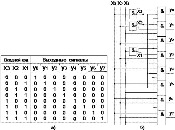
комбинационная схема, преобразующее n-разрядный двоичныйв -ичный одноединичный (позиционный) код
entity dc isport( x :instd_logic_vector(2downto0);
y :outstd_logic_vector(7downto0));end dc;architecture beh of dc isbegin
y <="00000001"when x ="000"else"00000010"when x ="001"else"00000100"when x ="010"else"00001000"when x ="011"else"00010000"when x ="100"else"00100000"when x ="101"else"01000000"when x ="110"else"10000000"when x ="111"else"00000000";end beh;
libraryIEEE;useIEEE.STD_LOGIC_1164. all;useIEEE.NUMERIC_STD. all;entity Decoder isport( Din :inSTD_LOGIC_VECTOR(2downto0);
Dout:outSTD_LOGIC_VECTOR(7downto0));end Decoder;architecture Synt of Decoder isbegin
Dout <="00000001"sll TO_INTEGER (UNSIGNED(Din));end Synt;
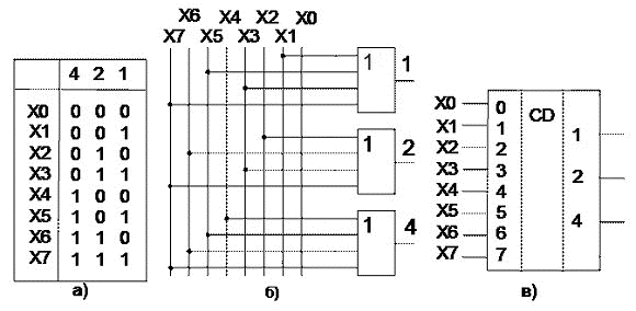
entity cd isport(
x :instd_logic_vector(7downto0);
y :outstd_logic_vector(2downto0));end dc;architecture beh1 of cd isbegin
y <="000"when x(0)="1"else"001"when x(1)="1"else"010"when x(2)="1"else"011"when x(3)="1"else"100"when x(4)="1"else"101"when x(5)="1"else"110"when x(6)="1"else"111"when x(7)="1"else"000";end beh1;
entity cd isport(
x :instd_logic_vector(7downto0);
y :outstd_logic_vector(2downto0));end dc;architecture beh2 of cd isbegin
y(0)<= x(1)or x(3)or x(5)or x(7);
y(1)<= x(2)or x(3)or x(6)or x(7);
y(2)<= x(4)or x(5)or x(6)or x(7);end beh2;
комбинационная схема, которая передает сигнал с одного из информационных входов Xi на единственный выход Y, причем номер выбираемого входа задается с помощью управляющих сигналов (адресных входов ai).
y = OE(x0*a1*a0 + x1*a1*a0 + x2*a1*a0 + x3*a1*a0)
Слайд:Мультиплексор (Схема)
Слайд:Мультиплексор (VHDL модель)
entity mux isport( x :instd_logic_vector(3downto0);
a :instd_logic_vector(1downto0);
y :outstd_logic);end mux;architecture beh of mux isbegin
y <= x(0)when a ="00"else
x(1)when a ="01"else
x(2)when a ="10"else
x(3)when a ="11"else '0';end beh;
libraryIEEE;useieee.std_logic_1164.all;useieee.numeric_std.all;entity Mux8 isport(x :instd_logic_vector(7downto0);
a :instd_logic_vector(2downto0);
y :outSTD_LOGIC);end Mux8;architecture Synthesis_1 of Mux8 isbeginprocess(x, a)begin
y <= x(TO_INTEGER (UNSIGNED(a)));endprocess;end Synthesis_1;
Слайд:Мультиплексор (Особенность)
с помощью мультиплексора можно реализовать любую логическую функцию
Слайд: Демультиплексор
комбинационная схема, которая выполняет функцию, обратную мультиплексору, т.е. в соответствии с принятой адресацией Ai направляет информацию с единственного входа D на один из M выходов Fj. При этом на остальных выходах будут логические нули (единицы).
Входы
Выходы
A1
A0
F3
F2
F1
F0
0
0
0
0
0
D
0
1
0
0
D
0
1
0
0
D
0
0
1
1
D
0
0
0
Слайд: Демультиплексор (Схема)
Слайд: Демультиплексор (VHDL модель)
entity dms isport( x :instd_logic;
a :instd_logic_vector(1downto0);
y :outstd_logic_vector(3downto0));end dms;architecture beh of dms isbegin
y <="000"& x when a ="00"else"00"& x & '0' when a ="01"else
'0' & x &"00"when a ="10"else
x &"000"when a ="11"else"0000";end beh;
Слайд:ПЗУ
ПЗУ(n,m) предназначено для хранения информации – 2n двоичных слов, каждое слово имеет m разрядов. Объем ПЗУ(n,m) – число бит хранимой информации подсчитывается по формуле
SПЗУ = 2n m (бит)
Заметим, что данная формула отражает сложность ПЗУ(n,m) весьма приближенно – в расчет не принимается сложность дешифратора.
На ПЗУ могут быть реализованы комбинационные схемы, функционирование которых представляется таблицей истинности системы булевых функций. При этом в ПЗУ "записывается" правая часть таблицы – значения функций на всех наборах булева пространства входных переменных.
Например, ПЗУ(4, 7), приведенное на рисунке, реализует функции, заданные данной таблицей истинности.
Слайд:ПЗУ (VHDL модель)
Приведенное ниже описание (VHDL-код) позволяет моделировать конкретное ПЗУ(4, 7), т.е. ПЗУ, хранящее определенный набор двоичных словю.
Хранимые данные (биты) описываются константой hex_to_7 типа rom_type.
package pack_ROM istype seven_segment isarray(6downto0)ofbit;type rom_type isarray(naturalrange<>)of seven_segment ;constant hex_to_7 : rom_type (0to15):=("0111111", -- адрес 0"0011000", -- адрес 1"1101111", -- адрес 2"1111100", -- адрес 3"1011010", -- адрес 4"1110110", -- адрес 5"1110111", -- адрес 6"0011100", -- адрес 7"1111111", -- адрес 8"1111110", -- адрес 9"1011111", -- адрес 10"1110011", -- адрес 11"0100111", -- адрес 12"1111001", -- адрес 13"1100111", -- адрес 14"1000111");-- адрес 15end pack_ROM;packagebody pack_ROM isend pack_ROM;
Слайд: VHDL-минимум для описания триггеров. Оператор Process (3)
Оператор процесса
LABEL: process [ ( имя сигнала {, имя сигнала } ) ]
объявление в процессеbeginпоследовательный оператор[ы]endprocess;
Пример
Пример c process
Сокращённая запись
entity A2 isport(
A, B :instd_logic;
C :outstd_logic);end A2;architecture beh of A2 isbeginprocess(A, B)begin
C <= A and B;endprocess;end beh;
entity A2 isport(
A, B :instd_logic;
C :outstd_logic);end A2;architecture beh of A2 isbegin
C <= A and B;end beh;
Слайд: VHDL-минимум для описания триггеров. Оператор if
Оператор условия if (последовательный оператор)
if Условие_1 then
Выражение1
elsif Условие_2 then
Выражение2
else
Выражение3
endif;
Пример 1
Пример 2
IF(s0='0' AND s1='0')THEN
output <= in0;ELSIF(s0='1' AND s1='0')THEN
output <= in1;ELSE
output <= 'X';ENDIF;
IF(s0='0' AND s1='0')THEN
output <= in0;ELSE
output <= 'X';ENDIF;
Пример 3
Пример 4
IF(s0='0' AND s1='0')THEN
output <= in0;ELSIF(s0='1' AND s1='0')THEN
output <= 'X';ENDIF;
IF(s0='0' AND s1='0')THEN
output <= in0;ENDIF;
Слайд: VHDL-минимум для описания триггеров (4)
D-Триггер без сброса
DFF:process(CLOCK)beginifCLOCK'EVENTandCLOCK= '1' then
Q <= D;-- тактироваие передним фронтомendif;endprocess;
D-Триггер со сбросом и установкой
AS_DFF:process(CLOCK, RESET, SET)beginif RESET = '1' then
Q <= '0';elsif SET = '1' then
Q <= '1';elsifCLOCK'EVENTandCLOCK= '1' then
Q <= D;endif;endprocess;
Слайд: VHDL-модели триггеров (fdp)
D-Триггер, синхронизируемый положительным фронтом, с парафазным выходом
libraryieee;useieee.std_logic_1164.all;entity fdp is-- pragma synthesis_offgeneric(
del :time:=900ps);-- pragma synthesis_onport(
d :instd_logic;
c :instd_logic;
q :outstd_logic;
qn :outstd_logic);end fdp;architecture beh of fdp isbegin
p1 :process(c)beginif c'eventand c = '1' then
q <= to_x01(d)after del;
qn <=not to_x01(d)after del;endif;endprocess p1;end beh;
Слайд: VHDL-модели триггеров (fld)
D-Триггер, синхронизируемый отрицательным фронтом
libraryieee;useieee.std_logic_1164.all;entity fld is-- pragma synthesis_offgeneric(
del :time:=900ps);-- pragma synthesis_onport(
d :instd_logic;
c :instd_logic;
q :outstd_logic);end fld;architecture beh of fld isbegin
p1 :process(c)beginif c'eventand c = '0' then
q <= to_x01(d)after del;endif;endprocess p1;end beh;
Слайд: VHDL-модели триггеров (fdrs)
D-Триггер, синхронизируемый положительным фронтом, с асинхронным сбросом и установкой
libraryieee;useieee.std_logic_1164.all;entity fdrs is-- pragma synthesis_offgeneric(
del :time:=900ps);-- pragma synthesis_onport(
d :instd_logic;
c :instd_logic;
r :instd_logic;
s :instd_logic;
q :outstd_logic);end fdrs;architecture beh of fdrs isbegin
p1 :process(r, s, c)beginif r = '1' then
q <= '0' after del;elsif s = '1' then
q <= '1' after del;elsif c'eventand c = '1' then
q <= to_x01(d)after del;endif;endprocess p1;end beh;
D-Триггер, синхронизируемый положительным фронтом, с асинхронным сбросом
libraryieee;useieee.std_logic_1164.all;entity fdr is-- pragma synthesis_offgeneric(
del :time:=900ps);-- pragma synthesis_onport(
d :instd_logic;
c :instd_logic;
r :instd_logic;
q :outstd_logic);end fdr;architecture beh of fdr isbegin
ff :process(r, c)beginif r = '1' then
q <= '0' after del;elsif c'eventand c = '1' then
q <= to_x01(d)after del;endif;endprocess ff;end beh;
D-Триггер (fdrp) с прямым и инверсным выходом, синхронизируемый положительным фронтом, с асинхронным сбросом
—
libraryieee;useieee.std_logic_1164.all;entity fdrp is-- pragma synthesis_offgeneric(
del :time:=900ps);-- pragma synthesis_onport(
d :instd_logic;
c :instd_logic;
r :instd_logic;
q :outstd_logic;
qn:outstd_logic);end fdrp;architecture beh of fdrp isbegin
ff :process(r, c)beginif r = '1' then
q <= '0' after del;
qn <= '1' after del;elsif c'eventand c = '1' then
q <= to_x01(d)after del;
qn <=not to_x01(d)after del;endif;endprocess ff;end beh;
D-Триггер с сигналом разрешения записи данных, синхронизируемый положительным фронтом
libraryieee;useieee.std_logic_1164.all;entity fe is-- pragma synthesis_offgeneric(
del :time:=900ps);-- pragma synthesis_onport(
d :instd_logic;
e :instd_logic;
c :instd_logic;
q :outstd_logic);end fe;architecture beh of fe isbegin
p1 :process(c)beginif c'eventand c = '1' thenif e = '1' then
q <= to_x01(d)after del;endif;endif;endprocess p1;end beh;
D-Триггер с сигналом разрешения записи данных, синхронизируемый положительным фронтом, с асинхронным сбросом и установкой
libraryieee;useieee.std_logic_1164.all;entity fers is-- pragma synthesis_offgeneric(
del :time:=900ps);-- pragma synthesis_onport(
d :instd_logic;
e :instd_logic;
c :instd_logic;
r :instd_logic;
s :instd_logic;
q :outstd_logic);end fers;architecture beh of fers isbegin
p1 :process(r, s, c)beginif r = '1' then
q <= '0' after del;elsif s = '1' then
q <= '1' after del;elsif c'eventand c = '1' thenif e = '1' then
q <= to_x01(d)after del;endif;endif;endprocess p1;end beh;
D-Триггер, синхронизируемый положительным уровнем
libraryieee;useieee.std_logic_1164.all;entity ld is-- pragma synthesis_offgeneric(
del :time:=900ps);-- pragma synthesis_onport(
d :instd_logic;
c :instd_logic;
q :outstd_logic);end ld;architecture beh of ld isbegin
p1 :process(c, d)beginif c = '1' then
q <= to_x01(d);endif;endprocess p1;end beh;
D-Триггер, синхронизируемый положительным уровнем, с асинхронным сбросом
libraryieee;useieee.std_logic_1164.all;entity ldr is-- pragma synthesis_offgeneric(
del :time:=900ps);-- pragma synthesis_onport(
d :instd_logic;
c :instd_logic;
r :instd_logic;
q :outstd_logic);end ldr;architecture beh of ldr isbegin
p1 :process(r, c, d)beginif r = '1' then
q <= '0' after del;elsif c='1' then
q <= to_x01(d)after del;endif;endprocess p1;end beh;
асинхронный RS-триггер
libraryieee;useieee.std_logic_1164.all;entity lrs is-- pragma synthesis_offgeneric(
del :time:=900ps);-- pragma synthesis_onport(
r :instd_logic;
s :instd_logic;
q :outstd_logic);end lrs;architecture beh of lrs isbegin
p1 :process(r, s)beginif r = '1' then
q <= '0' after del;elsif s = '1' then
q <= '1' after del;endif;endprocess p1;end beh;
D-Триггер, синхронизируемый низким уровнем
libraryieee;useieee.std_logic_1164.all;entity lld is-- pragma synthesis_offgeneric(
del :time:=900ps);-- pragma synthesis_onport(
d :instd_logic;
cl :instd_logic;
q :outstd_logic);end lld;architecture beh of lld isbegin
p1 :process(cl, d)beginif cl = '0' then
q <= to_x01(d)after del;endif;endprocess p1;end beh;
T-триггер, синхронизируемый положительным фронтом
libraryieee;useieee.std_logic_1164.all;entity fts is-- pragma synthesis_offgeneric(
del :time:=900ps);-- pragma synthesis_onport(
c :instd_logic;
s :instd_logic;
q :outstd_logic);end fts;architecture beh of fts issignal q_i :std_logic;begin
ff :process(s, c)beginif s = '1' then
q_i <= '1' after del;elsif c'eventand c = '1' then
q_i <=not q_i after del;endif;endprocess ff;
q <= q_i;end beh;