В алгебре логики известны три основные логические операции:
Логическое умножение (конъюнкция или операция И). Записывается как F = A Λ B, F = A & B, F = A·B, F = AB, читается – A и B.
Логическое сложение (дизъюнкция или операция ИЛИ). Записывается как F = A V B, F = A | B, F = A+B, читается – F = A или B.
Логическое отрицание (инверсия или операция НЕ). Записывается F = A , читается – F = “не” A.
Слайд:Таблица истинности логических элементов
Аргументы
Логические операции (булевы функции)
А
В
И
ИЛИ
НЕ
A·B
A+B
A
B
0
0
0
0
1
1
0
1
0
1
1
0
1
0
0
1
0
1
1
1
1
1
0
0
Операторы VHDL
A and B
A or B
not A
not B
Комментарий
Таким образом, выполнение сколь угодно сложной логической операции может быть сведено к трем вышеперечисленным операциям. Следовательно, имея некоторые технические устройства, реализующие операции И, ИЛИ, НЕ, можно построить сколь угодно сложное цифровое устройство. Такие устройства называются соответственно логическими элементами И, ИЛИ, НЕ (рис. 2) и образуют основной базис или функционально полную систему логических элементов.
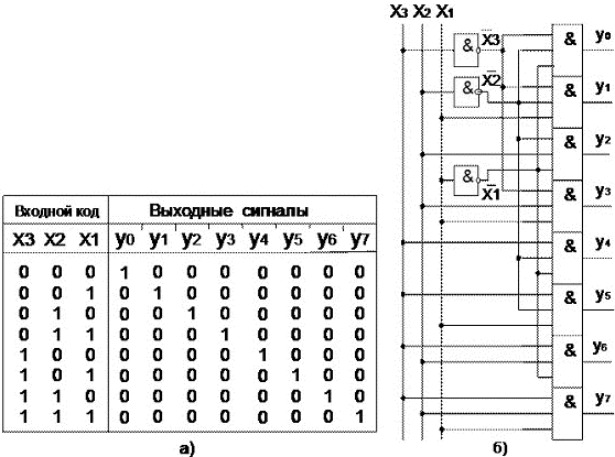
entity dc isport(
x :instd_logic_vector(2downto0);
y :outstd_logic_vector(7downto0));end dc;architecture beh of dc isbegin
y <="00000001"when x ="000"else"00000010"when x ="001"else"00000100"when x ="010"else"00001000"when x ="011"else"00010000"when x ="100"else"00100000"when x ="101"else"01000000"when x ="110"else"10000000"when x ="111"else"00000000";end beh;
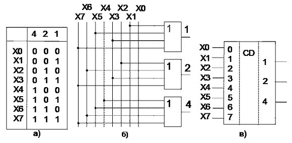
entity cd isport(
x :instd_logic_vector(7downto0);
y :outstd_logic_vector(2downto0));end dc;architecture beh1 of cd isbegin
y <="000"when x(0)="1"else"001"when x(1)="1"else"010"when x(2)="1"else"011"when x(3)="1"else"100"when x(4)="1"else"101"when x(5)="1"else"110"when x(6)="1"else"111"when x(7)="1"else"000";end beh1;
entity cd isport(
x :instd_logic_vector(7downto0);
y :outstd_logic_vector(2downto0));end dc;architecture beh2 of cd isbegin
y(0)<= x(1)or x(3)or x(5)or x(7);
y(1)<= x(2)or x(3)or x(6)or x(7);
y(2)<= x(4)or x(5)or x(6)or x(7);end beh2;
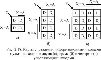
комбинационная схема, которая передает сигнал с одного из информационных входов Xi на единственный выход Y, причем номер выбираемого входа задается с помощью управляющих сигналов (адресных входов ai).
entity mux isport(
x :instd_logic_vector(3downto0);
a :instd_logic_vector(1downto0);
y :outstd_logic);end mux;architecture beh of mux isbegin
y <=
x(0)when a ="00"else
x(1)when a ="01"else
x(2)when a ="10"else
x(3)when a ="11"else
'0';end beh;
Слайд:Мультиплексор (Особенность)
с помощью мультиплексора можно реализовать любую логическую функцию
комбинационная схема, которая выполняет функцию, обратную мультиплексору, т.е. в соответствии с принятой адресацией Ai направляет информацию с единственного входа D на один из M выходов Fj. При этом на остальных выходах будут логические нули (единицы).
entity dms isport(
x :instd_logic;
a :instd_logic_vector(1downto0);
y :outstd_logic_vector(3downto0));end dms;architecture beh of dms isbegin
y <="000"& x when a ="00"else"00"& x & '0' when a ="01"else
'0' & x &"00"when a ="10"else
x &"000"when a ="11"else"0000";end beh;
DFF:process(CLOCK)beginifCLOCK'EVENTandCLOCK= '1' then
Q <= D;-- тактироваие передним фронтомendif;endprocess;
D-Триггер со сбросом и установкой
AS_DFF:process(CLOCK, RESET, SET)beginif RESET = '1' then
Q <= '0';elsif SET = '1' then
Q <= '1';elsifCLOCK'EVENTandCLOCK= '1' then
Q <= D;endif;endprocess;
Слайд: VHDL-модели триггеров (fdp)
D-Триггер, синхронизируемый положительным фронтом, с парафазным выходом
libraryieee;useieee.std_logic_1164.all;entity fdp is-- pragma synthesis_offgeneric(
del :time:=900ps);-- pragma synthesis_onport(
d :instd_logic;
c :instd_logic;
q :outstd_logic;
qn :outstd_logic);end fdp;architecture beh of fdp isbegin
p1 :process(c)beginif c'eventand c = '1' then
q <= to_x01(d)after del;
qn <=not to_x01(d)after del;endif;endprocess p1;end beh;
Слайд: VHDL-модели триггеров (fld)
D-Триггер, синхронизируемый отрицательным фронтом
libraryieee;useieee.std_logic_1164.all;entity fld is-- pragma synthesis_offgeneric(
del :time:=900ps);-- pragma synthesis_onport(
d :instd_logic;
c :instd_logic;
q :outstd_logic);end fld;architecture beh of fld isbegin
p1 :process(c)beginif c'eventand c = '0' then
q <= to_x01(d)after del;endif;endprocess p1;end beh;
Слайд: VHDL-модели триггеров (fdrs)
D-Триггер, синхронизируемый положительным фронтом, с асинхронным сбросом и установкой
libraryieee;useieee.std_logic_1164.all;entity fdrs is-- pragma synthesis_offgeneric(
del :time:=900ps);-- pragma synthesis_onport(
d :instd_logic;
c :instd_logic;
r :instd_logic;
s :instd_logic;
q :outstd_logic);end fdrs;architecture beh of fdrs isbegin
p1 :process(r, s, c)beginif r = '1' then
q <= '0' after del;elsif s = '1' then
q <= '1' after del;elsif c'eventand c = '1' then
q <= to_x01(d)after del;endif;endprocess p1;end beh;
D-Триггер, синхронизируемый положительным фронтом, с асинхронным сбросом
libraryieee;useieee.std_logic_1164.all;entity fdr is-- pragma synthesis_offgeneric(
del :time:=900ps);-- pragma synthesis_onport(
d :instd_logic;
c :instd_logic;
r :instd_logic;
q :outstd_logic);end fdr;architecture beh of fdr isbegin
ff :process(r, c)beginif r = '1' then
q <= '0' after del;elsif c'eventand c = '1' then
q <= to_x01(d)after del;endif;endprocess ff;end beh;
D-Триггер (fdrp) с прямым и инверсным выходом, синхронизируемый положительным фронтом, с асинхронным сбросом
—
libraryieee;useieee.std_logic_1164.all;entity fdrp is-- pragma synthesis_offgeneric(
del :time:=900ps);-- pragma synthesis_onport(
d :instd_logic;
c :instd_logic;
r :instd_logic;
q :outstd_logic;
qn:outstd_logic);end fdrp;architecture beh of fdrp isbegin
ff :process(r, c)beginif r = '1' then
q <= '0' after del;
qn <= '1' after del;elsif c'eventand c = '1' then
q <= to_x01(d)after del;
qn <=not to_x01(d)after del;endif;endprocess ff;end beh;
D-Триггер с сигналом разрешения записи данных, синхронизируемый положительным фронтом
libraryieee;useieee.std_logic_1164.all;entity fe is-- pragma synthesis_offgeneric(
del :time:=900ps);-- pragma synthesis_onport(
d :instd_logic;
e :instd_logic;
c :instd_logic;
q :outstd_logic);end fe;architecture beh of fe isbegin
p1 :process(c)beginif c'eventand c = '1' thenif e = '1' then
q <= to_x01(d)after del;endif;endif;endprocess p1;end beh;
D-Триггер с сигналом разрешения записи данных, синхронизируемый положительным фронтом, с асинхронным сбросом и установкой
libraryieee;useieee.std_logic_1164.all;entity fers is-- pragma synthesis_offgeneric(
del :time:=900ps);-- pragma synthesis_onport(
d :instd_logic;
e :instd_logic;
c :instd_logic;
r :instd_logic;
s :instd_logic;
q :outstd_logic);end fers;architecture beh of fers isbegin
p1 :process(r, s, c)beginif r = '1' then
q <= '0' after del;elsif s = '1' then
q <= '1' after del;elsif c'eventand c = '1' thenif e = '1' then
q <= to_x01(d)after del;endif;endif;endprocess p1;end beh;
D-Триггер, синхронизируемый положительным уровнем
libraryieee;useieee.std_logic_1164.all;entity ld is-- pragma synthesis_offgeneric(
del :time:=900ps);-- pragma synthesis_onport(
d :instd_logic;
c :instd_logic;
q :outstd_logic);end ld;architecture beh of ld isbegin
p1 :process(c, d)beginif c = '1' then
q <= to_x01(d);endif;endprocess p1;end beh;
D-Триггер, синхронизируемый положительным уровнем, с асинхронным сбросом
libraryieee;useieee.std_logic_1164.all;entity ldr is-- pragma synthesis_offgeneric(
del :time:=900ps);-- pragma synthesis_onport(
d :instd_logic;
c :instd_logic;
r :instd_logic;
q :outstd_logic);end ldr;architecture beh of ldr isbegin
p1 :process(r, c, d)beginif r = '1' then
q <= '0' after del;elsif c='1' then
q <= to_x01(d)after del;endif;endprocess p1;end beh;
асинхронный RS-триггер
libraryieee;useieee.std_logic_1164.all;entity lrs is-- pragma synthesis_offgeneric(
del :time:=900ps);-- pragma synthesis_onport(
r :instd_logic;
s :instd_logic;
q :outstd_logic);end lrs;architecture beh of lrs isbegin
p1 :process(r, s)beginif r = '1' then
q <= '0' after del;elsif s = '1' then
q <= '1' after del;endif;endprocess p1;end beh;
D-Триггер, синхронизируемый низким уровнем
libraryieee;useieee.std_logic_1164.all;entity lld is-- pragma synthesis_offgeneric(
del :time:=900ps);-- pragma synthesis_onport(
d :instd_logic;
cl :instd_logic;
q :outstd_logic);end lld;architecture beh of lld isbegin
p1 :process(cl, d)beginif cl = '0' then
q <= to_x01(d)after del;endif;endprocess p1;end beh;
T-триггер, синхронизируемый положительным фронтом
libraryieee;useieee.std_logic_1164.all;entity fts is-- pragma synthesis_offgeneric(
del :time:=900ps);-- pragma synthesis_onport(
c :instd_logic;
s :instd_logic;
q :outstd_logic);end fts;architecture beh of fts issignal q_i :std_logic;begin
ff :process(s, c)beginif s = '1' then
q_i <= '1' after del;elsif c'eventand c = '1' then
q_i <=not q_i after del;endif;endprocess ff;
q <= q_i;end beh;
Слайд: Счетчики. Классификация
Счетчиком называется цифровой блок, предназначенный для подсчета входных сигналов.